Imaging on a mesoSPIM BT
This is a case study in using the software to image with a mesoSPIM BT microscope.
Setting the beam parameters
Make sure the imaging chamber is empty or, if a sample is mounted, the sample is not in the beam path.
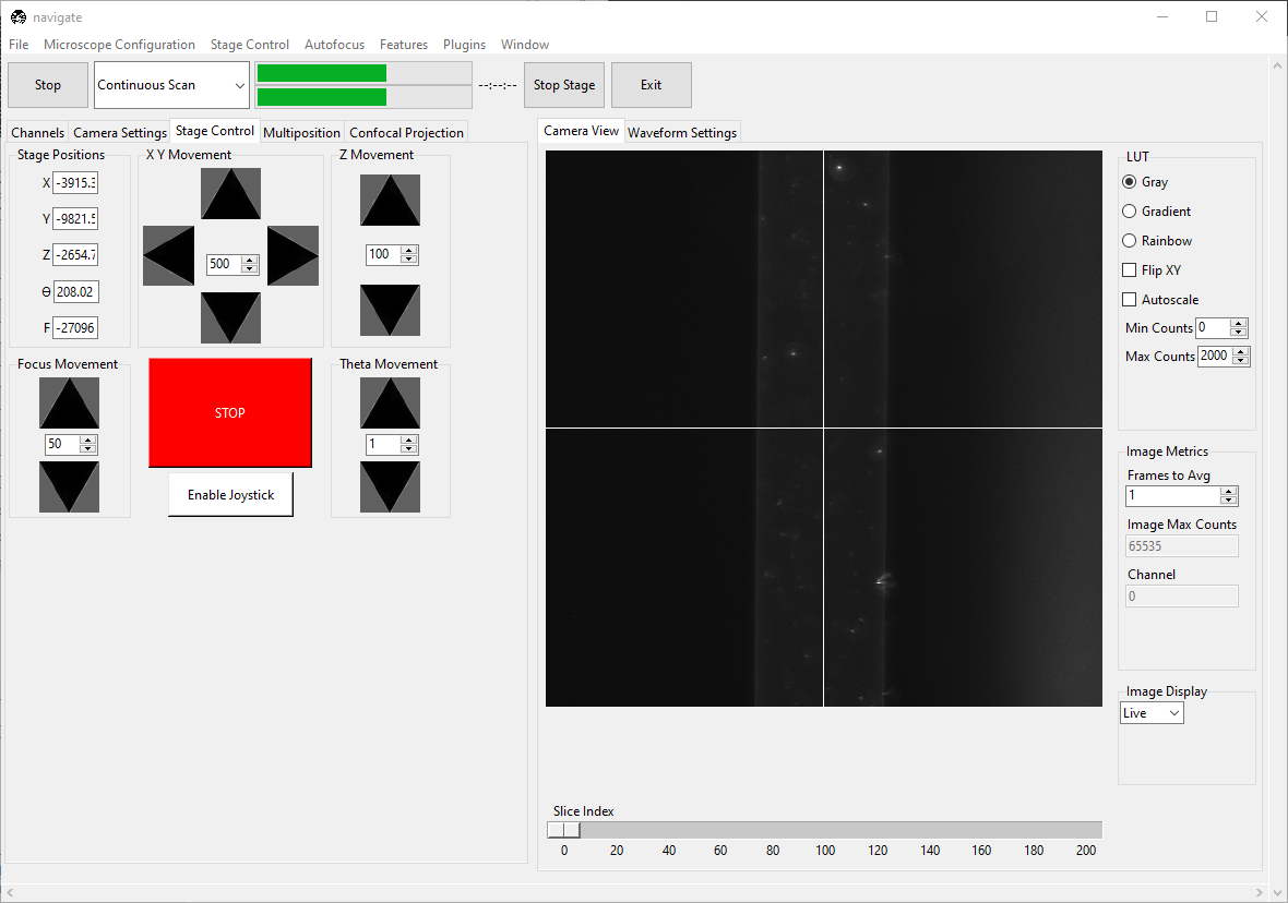
Select “Continuous Scan” from the dropdown next to the Acquire button. Press Acquire. This will launch a live acquisition mode.
Go to the Channels tab. Choose the wavelength you want to align. Set the laser’s Power to
100.0. Change Filter to an “Empty” option.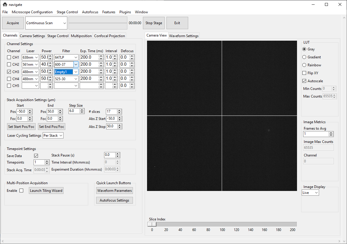
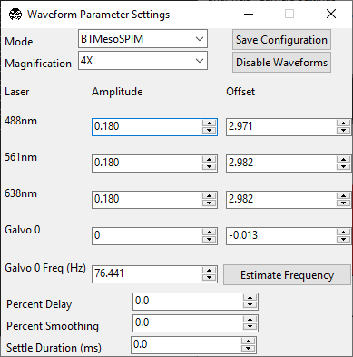
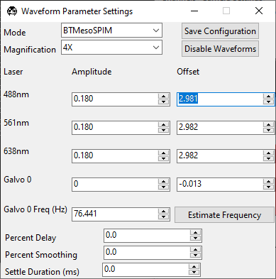
Go to the . A popup named Waveform Parameter Settings will appear. Make sure the Mode matches “mesoSPIM BT” and the Magnification matches the magnification of the objective you are using.
Note
The Mode is the name of the microscope as defined in the configuration.yaml file.
Likewise, the Magnification is the magnification(s) for that microscope as defined in the
configuration.yaml file.
The mesoSPIM BT largely operates at a fixed magnification. However, the original mesoSPIM used a variable magnification research grade macro zoom microscope.
Galvo 0 digitally sweeps the beam across the field of view in the
Xdirection. To align the axially-swept light sheet parameters, set the Galvo 0 Amplitude to0.0.
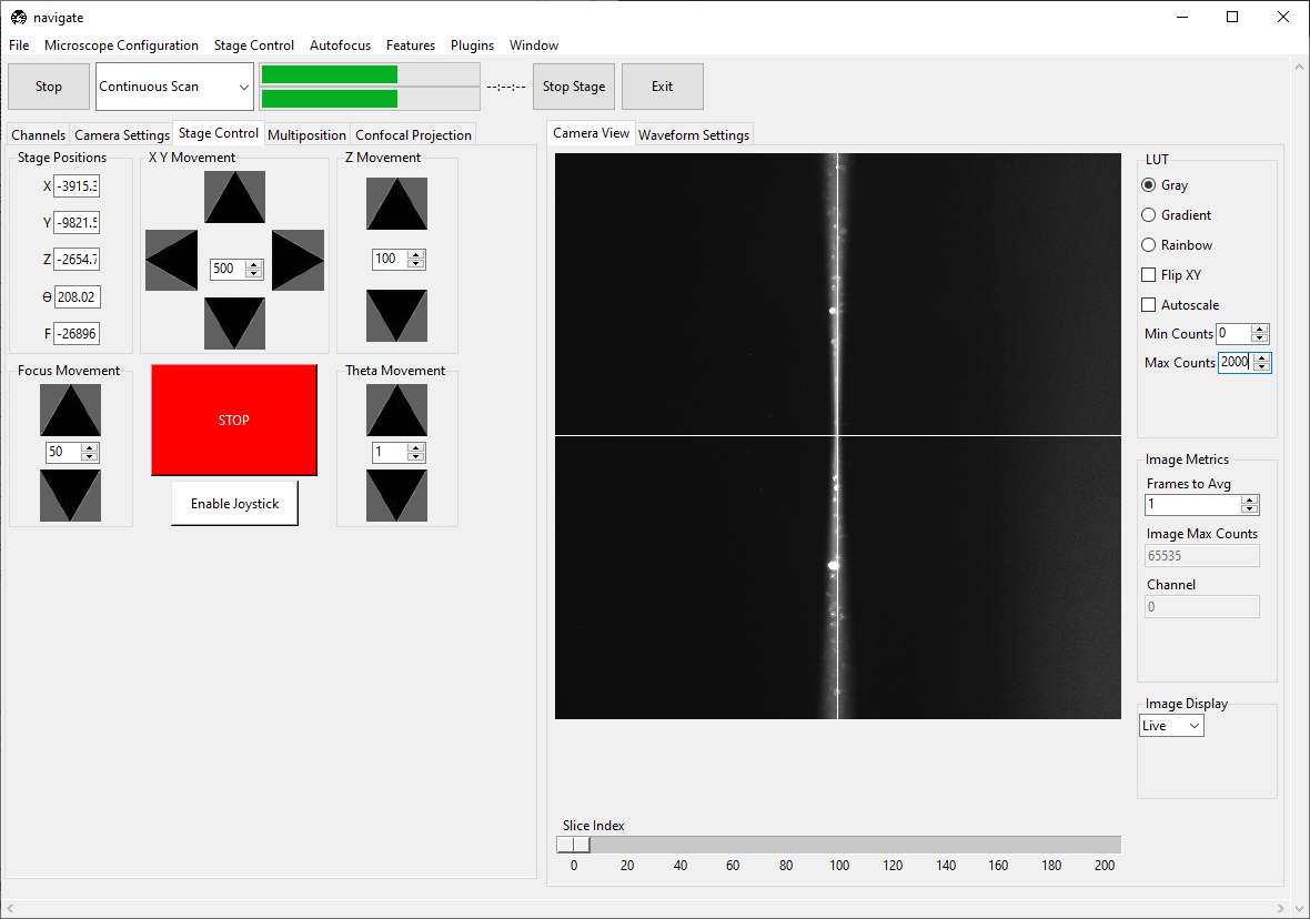
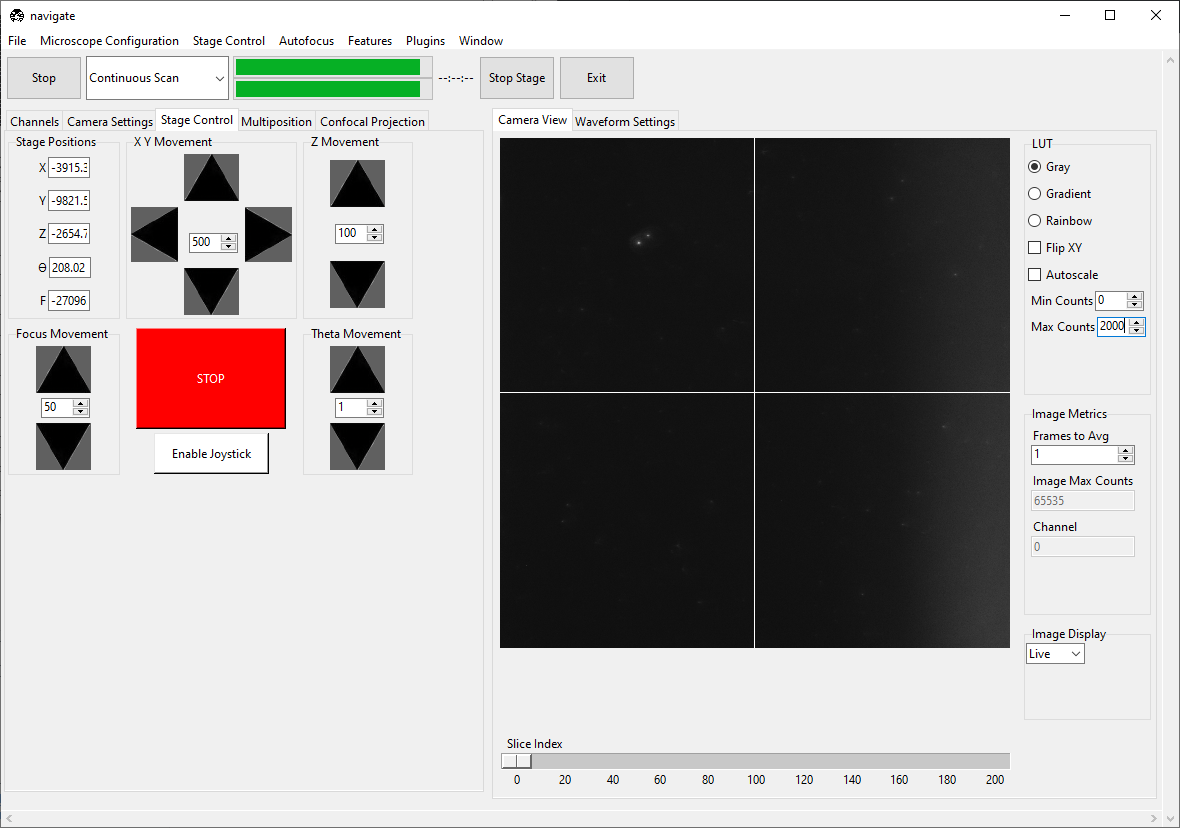
The empty filter makes us susceptible to seeing particles scattering light in the chamber. This can effect the software’s autoscaling routine. To ensure we are looking at the beam correctly, uncheck Autoscale and set the Min Counts and Max Counts so the beam is visible, but not saturating the display.
Set the wavelength’s Amplitude to
0.0. Set the wavelength’s Offset so that the beam is focused in the center of the field of view.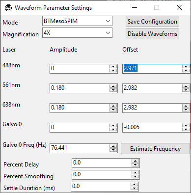
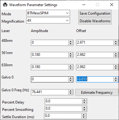
Set the Galvo 0 Offset so that the beam is centered in the field of view. Click the Camera View to toggle the crosshairs, which indicate the center of the field of view.
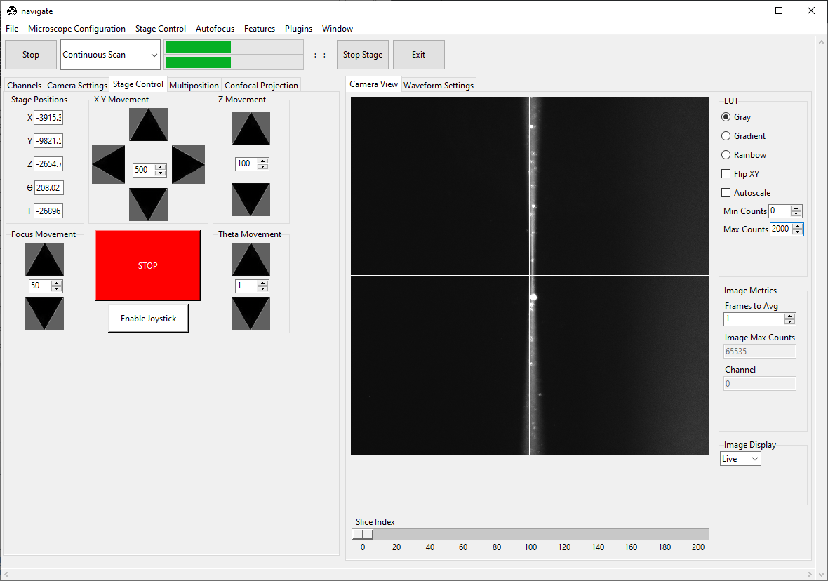
Go to Camera Settings and ensure that Light-Sheet is selected under Sensor Mode. Slowly increase the wavelength’s Amplitude until the beam becomes a straight line across the screen. If the beam does not become straighter, try changing the camera’s Readout Direction.
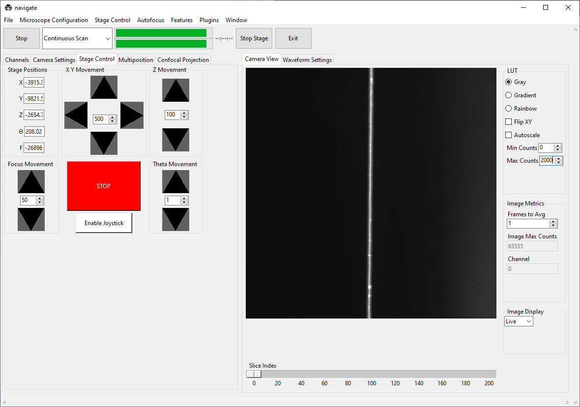
Adjust the F (focus) value in the Stage Control panel until the beam is as thin/focused as possible.
Once the beam is straight, slowly change the wavelength’s Offset until the beam has an even thickness across the field of view. This will also make the beam a bit thinner.

Warning
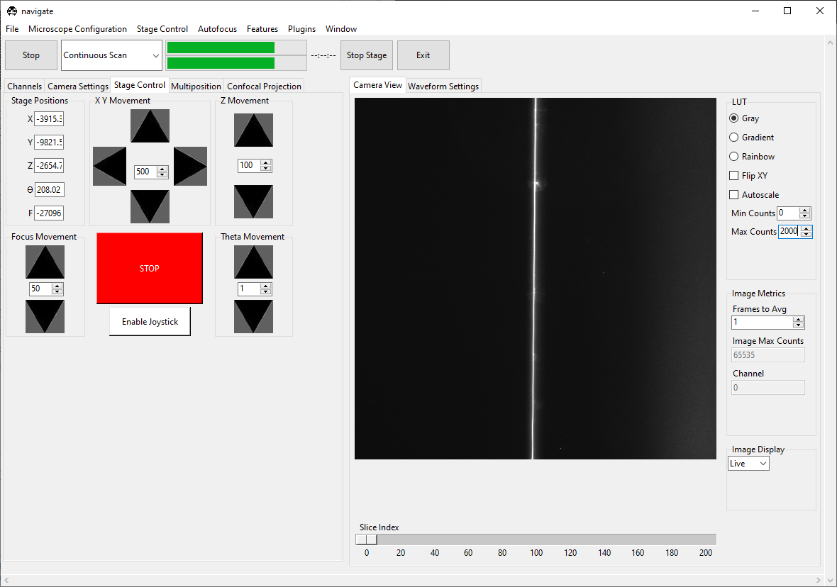
Proper alignment of the ASLM scan is critical to the quality of the image. We recommend iterating the Amplitude, Offset, and F until the beam is uniformly as thin as possible throughout the entire field of view.
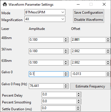
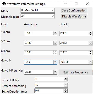
Slowly increase Galvo 0’s Amplitude until the entire field of view is just covered by the digitally scanned beam. Over-scanning the beam will result in a loss of light, but also provide a more uniform illumination for tiling applications.
Under Waveform Parameter Settings, press Save Configuration.
Under the Channels tab, restore the filter to its non-empty position.
Loading and finding the sample
Load the sample on the microscope.
Select “Continuous Scan” from the dropdown next to the Acquire button. Press Acquire. This will launch a live acquisition mode.
Scroll around with the stage either via joystick or using the controls in the Stage Control tab until the sample comes into view.
Focus on the sample using the
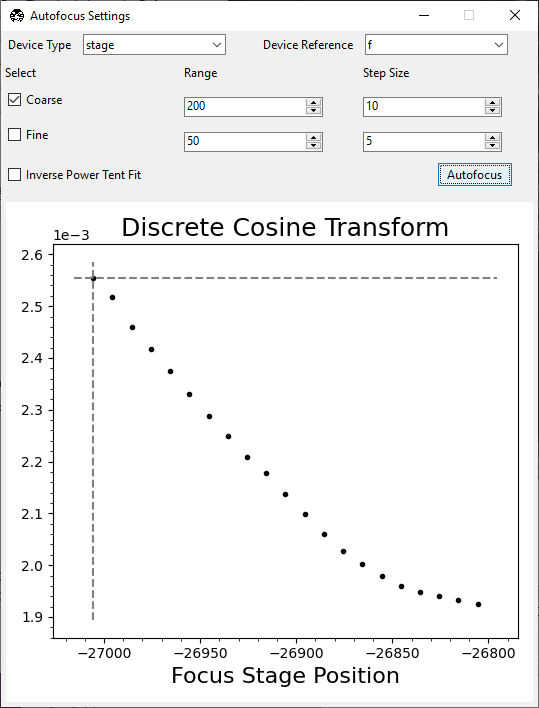
Faxis. Optionally, use Autofocus by going to . Press Autofocus. Ensure there is a clear peak in the resulting plot.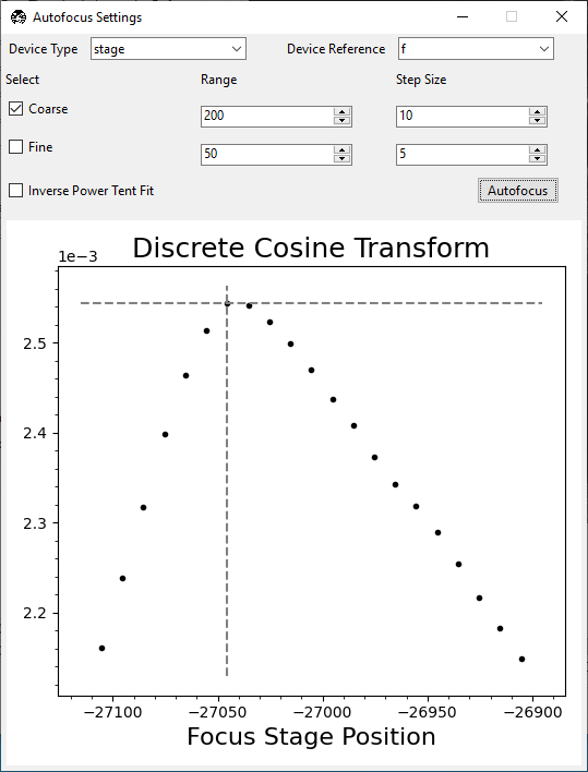
If there is not a clear peak, the autofocusing routine did not work. Try increasing the laser power and/or bringing the sample more into focus manually. If it did work, the sample should now be in focus.
Note
Sometimes there isn’t a clear peak, but there is a clear trend toward a peak. In this case, the autofocus is converging, but the true focus position is outside the range of your search. Run autofocus again to achieve convergence.
Imaging a z-stack
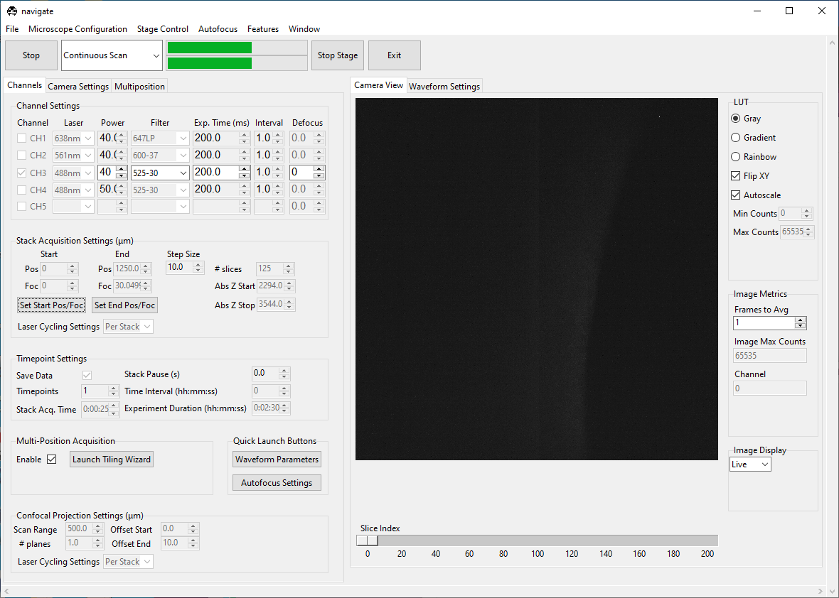
Select “Continuous Scan” from the dropdown next to the Acquire button. Press Acquire. This will launch a live acquisition mode.
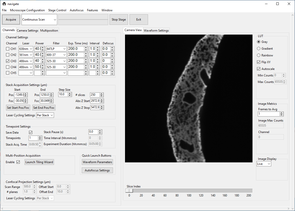
Using the Stage Control, go to a shallow Z-position in the sample. Under the Channels tab, in Stack Acquisition Settings (um) press Set Start Pos/Foc.
Go to a deep Z-position in the sample. Press Set End Pos/Foc.
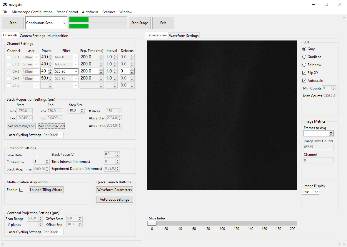
Select “Z-Stack” from the dropdown next to the Acquire button. Press Acquire.
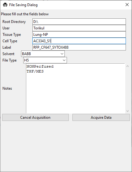
Enter the sample parameters in the File Saving Dialog that pops up. Press Acquire Data.
Tiling a sample larger than the field of view
This assumes you have already set the start and end positions in Stack Acquisition Settings (um) (see Imaging a Z-Stack).
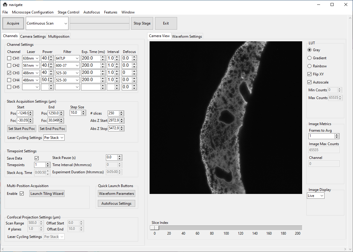
Under the Channels tab, press Launch Tiling Wizard.
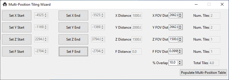
Go to thickest part of the sample. Go to the lower bound of the
Xaxis and press Set X Start. Go to the upper bound of theXaxis and press Set X End. Repeat for all axes except for focus.Ensure the sample is in focus and press Set F Start and Set F End without changing the focus position.
Press Populate Multi-Position Table. Navigate to the Multiposition tab and ensure the locations populated.
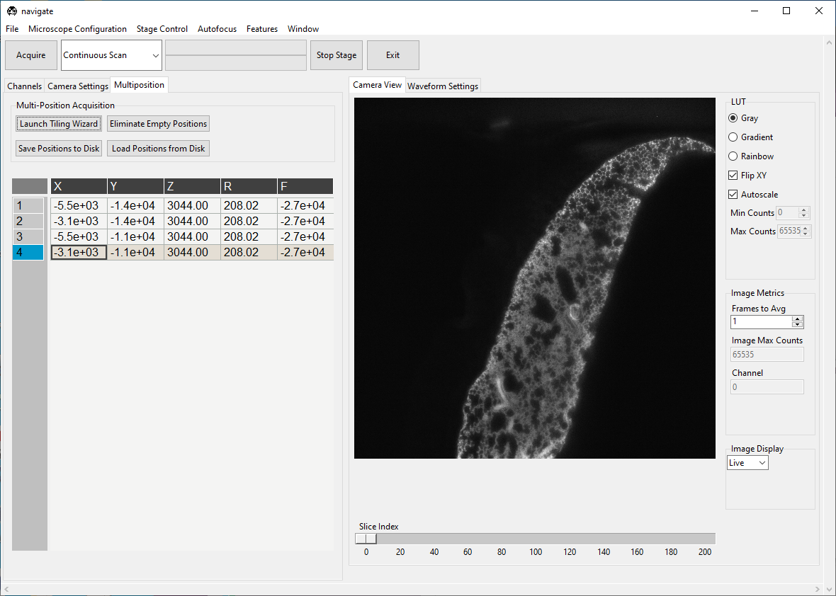
Under the Channels, make sure Enable is checked under Multi-Position Acquisition.
Under the Channels, make sure Save Data is checked under Timepoint Settings.
Select “Z-Stack” from the dropdown next to the Acquire button. Press Acquire.
Enter the sample parameters in the File Saving Dialog that pops up. Press Acquire Data.