Configuration Overview
This section outlines the configuration.yaml, experiment.yml,
rest_api_config.yml, waveform_templates.yml, and
waveform_constants.yml files.
Initial Configuration
In order for the navigate software to function, you will need to configure the
specifications of the various hardware that you will be using in the
configuration.yaml file.
An example configuration.yaml file is provided in the
navigate\config directory. However, to avoid conflicts between different
microscopes after pulling new changes from GitHub, navigate by default
loads a local version of the configuration.yaml file. This file is
stored in the C:\Users\Username\AppData\Local\.navigate\config directory
on Windows or ~/.navigate on Mac/Linux.
Configuration Wizard
To help you set up your configuration file, we have created a configuration wizard
that will guide you through the process of creating your
configuration.yaml file. To launch the configuration wizard, open your
Terminal or Anaconda Prompt, activate your navigate Python environment
and launch the software by typing: navigate -c.
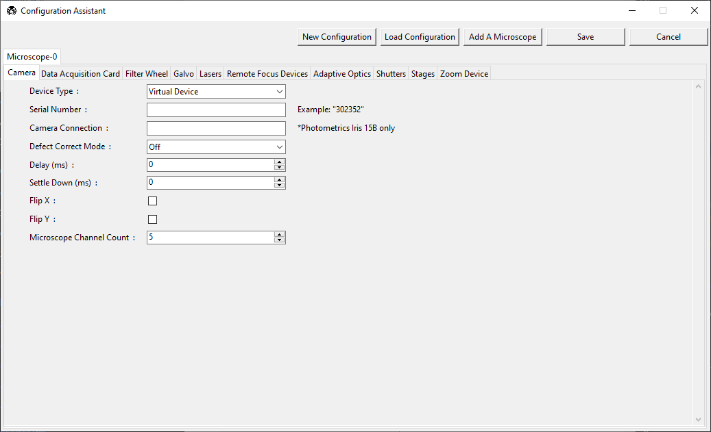
The configuration wizard provides a convenient way for configuring your hardware. For each microscope, which can be renamed or deleted by right-clicking on the microscope tab, you will be asked to specify the hardware that you are using. Each hardware type is listed as its own independent tab, and required parameters are shown on the left column, a field for the parameter is shown in the middle, and an example of the parameter is shown on the right.
Additional microscope instances can be added by clicking the
Add A Microscope button. Should one want to start from scratch, the
New Configuration button will clear the current configuration.
If you have a configuration that you would like to modify, you can load it by
clicking the Load Configuration button. Once you have completed
the configuration, you can save it by clicking the Save button.
For navigate to use the configuration file by default, it should be
saved as configuration.yaml in the following directory, depending upon
your operating system:
Windows:
C:\Users\Username\AppData\Local\.navigate\configMac/Linux:
~/.navigate
Note
The configuration wizard is actively being developed, and may not support every device type or configuration option. If you encounter any issues with the configuration wizard, please let us know by creating an issue on GitHub..
Manual Configuration
If you prefer to manually configure your configuration.yaml file, we
recommend launching the software in the synthetic hardware mode initially.
Within your Terminal, or Anaconda Prompt, activate your navigate
Python environment and launch the software in the synthetic hardware mode by
typing: navigate -sh.
Upon launching the software in the synthetic hardware mode, navigate will
create a copy of the navigate\config\configuration.yaml file in
C:\Users\Username\AppData\Local\.navigate\config on Windows or ~/
.navigate on Mac/Linux.
Thereafter, you should only modify the configuration.yaml file in your
local .navigate\config directory.
Tip
Once navigate is open in the synthetic hardware mode, you can open the
configuration.yaml file by going to menu and selecting
Open Configuration Files.
It may help to open
C:\Users\Username\AppData\Local\.navigate\config\configuration.yaml and follow
along in this file when reading the next sections.
See the Setting up an Axially Swept Light-Sheet Microscope case study for a general walkthrough of how to build your own configuration file and see Implementations for examples of configuration files.
Microscope Configurations
The configuration.yaml file contains the microscope configurations
that you will be using with the software. Each microscope is represented as a YAML
dictionary.
Switching between each microscope is readily performed in navigate, enabling you to switch between different configurations or imaging modes, each with their own unique or shared hardware:
microscopes:
    microscope1:
        ...
        ...
    microscope2:
        ...
        ...
Here, microscope1 and microscope2 are names of two different
microscopes using different combinations of the hardware. The names of
the microscopes must not include spaces or special characters such as <, \,
#, %, or ?.
Microscope Inheritance
When setting up a configuration.yaml file with multiple microscopes, the
file can grow quite large and repetitive, especially if the microscopes share
many of the same hardware components. To avoid this, navigate allows for
inheritance of hardware components from one microscope to another. In the
following example, microscope2 inherits all of the hardware components
from microscope1 except for the camera, since this is specified in the
microscope2 section.
microscopes:
    microscope1:
        camera:
            hardware:
                type: HamamatsuOrca
                ...
        ...
    microscope2(microscope1):
        camera:
            hardware:
                type: HamamatsuFusion
                ...
        ...
Microscope Hardware Specification
Each microscope is expected to have a daq, camera, remote_focus_device,
galvo, filter_wheel, stage, zoom, shutter, mirror and
lasers section of the YAML dictionary. As in the hardware section, unused devices
can be specified as synthetic.
Most of the information to set up these devices can be found in the
Supported Hardware section of the documentation.
Additional explanations of a few specific sections of the microscope configuration are
below. Notably, the zoom section of the configuration.yaml specifies effective
pixel size.
Stage Subsection
The stage section of the microscope 1) puts the stage control from the hardware
section into the microscope 2) sets boundaries for stage movement and 3) optionally
specifies joystick-controlled axes.
microscopes:
    microscope1:
        stage:
            hardware:
              -
                name: stage
                type: ASI
                serial_number: 123456789
                axes: [x, y, z, f] # Software
                axes_mapping: [M, Y, X, Z] # M Shear axis mapping

              -
                name: stage
                type: SyntheticStage
                serial_number: 987654321
                axes: [theta]

        joystick_axes: [x, y, z]
        x_max: 100000
        x_min: -100000
        y_max: 100000
        y_min: -100000
        z_max: 100000
        z_min: -100000
        f_max: 100000
        f_min: -100000
        theta_max: 360
        theta_min: 0

        x_offset: 0
        y_offset: 0
        z_offset: 0
        theta_offset: 0
        f_offset: 0

        flip_x: False
        flip_y: False
        flip_z: False
        flip_f: False
First, we set the axes controlled by each piece of hardware and a mapping from the
hardware’s API axes to our software’s axes. For example, the ASI M axis is mapped
onto our software’s X axis below.
For stages, navigate requires that stages are configured for each microscope
in X, Y, Z, F, and Theta. If no physical stage is present, then
that axes should be defined as a SyntheticStage, as shown above for Theta.
Below this, we specify that only X, Y and Z axes may be controlled by a
joystick and we set the stage bounds for each of the axes.
Below this, we set the minimum and maximum values for each axis. This can be used to set boundaries that prevent the stage from crashing into the sides of a chamber.
Below this, we set the offset for each stage axis. This is an offset relative to other
microscopes (e.g. microscope2) specified in configuration.yaml. In this case,
microscope1 is the reference microscope. Additional microscopes may ask the stage
to move to a different offset in order to observe the sample at the same position as
microscope1.
Finally, we set the flip flags. These are important for getting multiposition acquisitions to run properly. We set a convention in the software to expect that increasing value along an axis brings the sample further into our field of view. That is, increasing the x-axis position should bring the sample further to the right in the frame (in the case Flip XY is toggled on) and increasing the y-axis position should bring the sample down. Increasing the z-position should bring the sample closer to the objective. If the stage behaves the opposite of any of these ways, it is prudent to set the flip flag. If set properly, the calculations for moving through multiple positions will be performed correctly. These only need to be configured once when setting up the microscope.
Stage Axes Definition
Many times, the coordinate system of the stage hardware do not agree with the optical
definition of each axes identity. For example, many stages define their vertical
dimension as Z, whereas optically, we often define this axis as X. Thus, there
is often a need to map the mechanical axes to the optical axes, and this is done with
the axes_mapping dictionary entry in the stage hardware section. By default, stage
axes are read in as X, Y, Z, Theta, F, where Theta is rotation
and F is focus, but this can be changed by changing axes mapping.
axes: [x, y, z, theta, f]
axes_mapping: [x, y, z, r, f]
If, on a certain microscope, the Z stage axis corresponds to the optical Y-axis,
and vice versa, you would then have to import the stages as following:
axes: [x, y, z, theta, f]
axes_mapping: [x, z, y, r, f]
Joystick Axes Definition
If you are using a joystick, it is possible to disable GUI control of the stage axes that the joystick can interact with. The axes that the joystick can interact with appear in the stage field as following:
joystick_axes: [x, y, z]
Note
These axes should agree with the optical axes. If, on the same microscope
as mentioned in the Stage Axes Definition
section, the joystick were to control the optical y-axis corresponding to
the stage z axis, you would have to put Y in the joystick axes brackets
as following:
joystick_axes: [y]
Zoom Subsection
The zoom section of configuration.yaml specifies control over microscope
zoom lenses, or devices that change the magnifcation of the imaging system. For
example, we use the Dynamixel Smart Actuator to
control the rotating zoom wheel on an Olympus MVXPLAPO 1x/0.25.
microscopes:
    microscope1:
        zoom:
            hardware:
                name: zoom
                type: DynamixelZoom
                servo_id: 1
            position:
                0.63x: 0
                1x: 627
                2x: 1711
                3x: 2301
                4x: 2710
                5x: 3079
                6x: 3383
            pixel_size:
                0.63x: 9.7
                1x: 6.38
                2x: 3.14
                3x: 2.12
                4x: 1.609
                5x: 1.255
                6x: 1.044
            stage_positions:
                BABB:
                    f:
                        0.63x: 0
                        1x: 1
                        2x: 2
                        3x: 3
                        4x: 4
                        5x: 5
                        6x: 6
The positions specify the voltage of the actuator at different zoom positions.
The pixel_size specifies the effective pixel size of the system at each zoom. The
stage_positions account for focal shifts in between the different zoom values
(the MVXPLAPO does not have a consistent focal plane). These may change depending on
the immersion media. Here it is specified for a BABB (Benzyl Alcohol Benzyl
Benzoate) immersion media.
Regardless of whether or not your microscope uses a zoom device, you must have a
zoom entry, indicating the effective pixel size of your system in micrometers.
For example,
zoom:
  hardware:
    name: zoom
    type: SyntheticZoom
    servo_id: 1
  position:
    N/A: 0
  pixel_size:
    N/A: 0.168
Experiment File
The experiment.yml file stores information about the current state of the program.
This includes laser and camera parameters, saving options, z-stack settings and much
more. This file does not need to be edited by the user. The program will update it
automatically and save changes automatically on exit.
Waveform Constants File
The waveform_constants.yml file stores the waveform parameters that can be edited
by going to . This
file does not need to be edited by the user. The program will update it automatically
and save changes automatically on exit.
Waveform Templates File
The waveform templates file stores default behavior for the number of repeats for specific waveforms. This file only needs to be edited if the user wishes to introduce a new waveform behavior to the application.
Rest API Configuration File
The REST API configuration file specifies where the REST API should look to get and post data. This is only needed if you are using a plugin that requires the REST API, such as our communication with ilastik. More information on how to setup the REST API for communication with ilastik can be found here.