Data Acquisition Cards
Data acquisition cards deliver and receive analog and digital signals. To acquire an image, the software calculates all of the analog and digital waveforms and queues these waveforms on the data acquisition card. Upon receipt of a trigger (either from the software itself, or an external piece of hardware), all of the analog and digital signals are delivered in parallel. This provides deterministic behavior on a per-frame basis, which is necessary for proper acquisition of light-sheet data. It does not however provide us with deterministic behavior between image frames, and some jitter in timing is anticipated.
National Instruments (NI)
In principle, most NI-based data acquisition cards should work with the software, so long as there are a sufficient number of analog and digital ports, and the sampling rate (typically 100 kHz) is high enough per port.
Prior to installing the card within the computer, first install the NI-DAQmx drivers. Once installed, connect the PCIe or PXIe-based device to the computer. A functioning system should be recognized by the operating system, and visible in the Windows Device Manager as a NI Data Acquisition Device.
Note
navigate has been tested with the following versions of the NI-DAQmx drivers:
22.5.0
22.8.0
23.3.0
23.8.0
Tip
The most important aspect is to wire up the breakout box properly.
To find the device pin outs for your NI-based data acquisition card, open NI MAX, find the card under devices, right-click and select “device pinouts”.
Important: Should you use the SCB-68A breakout box, do not look at the pinout on the back of the cover. This is misleading. You must look at the device pinouts in NI MAX.
Note
For NI-based cards, port0/line1 is the equivalent of P0.1.
There are multiple pins for each PFIO, including source, out, gate, etc. You must
use the out terminal.
Identify the device name in NI MAX, and change it if you would like. Common names are
Dev1,Dev2, etc. This name must correspond with the pinouts provided in the configuration file.Connect the
master_trigger_out_lineto thetrigger_sourcewith a direct wire, commonlyPXI6259/port0/line1and/PXI6259/PFI0. In this example, the default name for the device (e.g.,Dev1) has been changed toPXI6259.Connect the
camera_trigger_out_lineto theExt. Triggeron the camera using theCTR0Outpin.These values must precisely match those in the configuration file. An example is provided below:
Configuration File
microscopes:
  microscope_name:
    daq:
        hardware:
          type: NI
        sample_rate: 10000
        master_trigger_out_line: PXI6259/port0/line1
        camera_trigger_out_line: /PXI6259/ctr0
        trigger_source: /PXI6259/PFIO
        laser_port_switcher: PXI6733/port0/line0
        laser_switch_state: False
navigate has been tested with the following NI-based cards:
PCIe/PXIe-6738
The PCIe-6738 can only create one software-timed analog task for every four channels. As such, the lasers much be attached to analog output ports outside of the banks (shown as solid lines in the device pinout) used by the galvo/remote focus units. For example, if you use ao0, ao2, and ao6 for the remote focus, galvo, and galvo stage, the lasers should be connected to ao8, ao9, and ao10. In such a configuration, they will not compete with the other analog output ports. Since only one task will be created created on the ao8, ao9, ao10 bank at a time (only one laser is on at a time), only one laser can be on at a time. If we wanted to turn lasers on simultaneously, we could distribute the lasers across independent banks (e.g. ao8, ao14, ao19).
Device Pinout

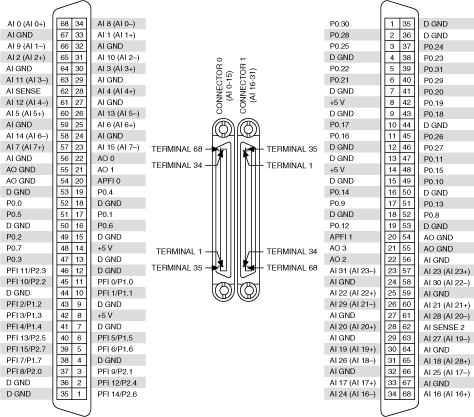
PCIe/PXIe-6259
The PXI-6259 can create one software-timed analog task per channel. As such, the
galvo/remote focus/lasers can be attached to any of the analog output ports. The 6259 has
two connectors, and it is important to make sure that the analog and digital ports that you
are using are connected to the correct connector. For example, if you are using ao0, this is
located on connector 0.
Device Pinout
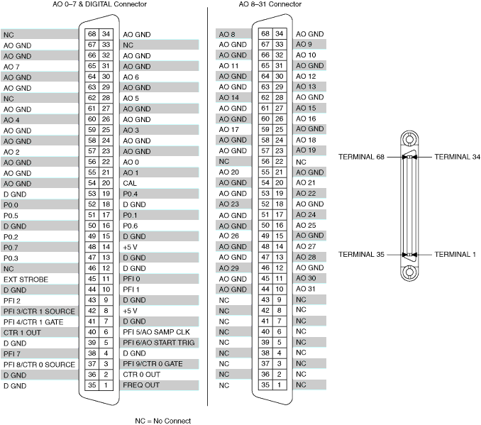
PCIe/PXIe-6723
The PXI-6723 can also create one software-timed analog task per channel. As such, the analog outputs can be wired up as is most convenient.
Device Pinout
Synthetic Data Acquisition Card
If no data acquisition card is present, one must configure the software to use a synthetic data acquisition card.
Configuration File
microscopes:
  microscope_name:
    daq:
        hardware:
          type: NI
        sample_rate: 10000
        master_trigger_out_line: PXI6259/port0/line1
        camera_trigger_out_line: /PXI6259/ctr0
        trigger_source: /PXI6259/PFIO
        laser_port_switcher: PXI6733/port0/line0
        laser_switch_state: False