Smart 3D Object Detection
Smart 3D Object Detection in navigate enables automated, feature-driven imaging across spatial scales. In this workflow, a specimen is first imaged volumetrically at a user-defined magnification using one microscope configuration—typically in a low-resolution, large field-of-view mode. A custom segmentation algorithm is then applied to the dataset to identify objects of interest in 3D. The positions of these detected features are automatically populated into the multiposition table. The system then switches to an alternatively configured microscope object—often operating at higher magnification and resolution—and revisits each detected location to acquire high-resolution image stacks. This streamlined process enables efficient, targeted imaging of biologically relevant features while minimizing unnecessary data acquisition.
This guide provides a step-by-step overview of how to set up and utilize the Volume Search 3D feature in navigate, which is essential for achieving high-resolution imaging of specific features within a larger volume.
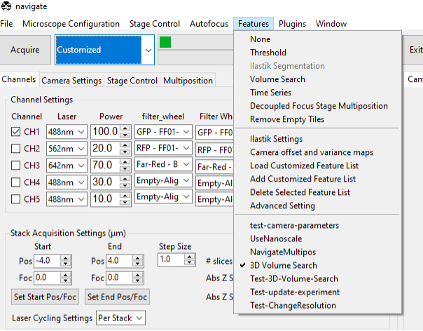
Configure the Low-Resolution Imaging Parameters:
Set the Z-scan range and step size. This low-resolution overview is used to identify targets.
Use a step size appropriate for the size of the features to be detected (e.g., glomeruli).
Load the Analysis Function:
Load the analysis function that will be used to detect the objects of interest. This function should be capable of processing the low-resolution images and identifying the features you want to target. Detailed directions on how to do this can be found in the Loading Custom Functions section of the documentation.
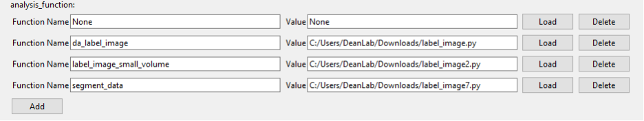
For the following example, we developed our own segmentation method:
from tifffile import imread, imwrite
from scipy import ndimage
import time
import dask.array as da
import skimage.filters as skfilters
import skimage.measure as skmeasure
import skimage.morphology as skmorph
import numpy as np


def threshold_block(block, threshold):
    return np.where(block >= threshold, 1, 0)

def segment_data(image):

    image =np.array(image)

    # Set all values above the 99.99th percentile to 100
    percentile = np.percentile(image[::4, ::4, ::4], 99.99)
    image = np.where(image > percentile, 100, image)
    print(f"Setting all values above {percentile} to 100.")

    # Convert to Dask Array
    dask_array = da.from_array(image.astype(np.float32), chunks=(256,256,256))

    # High-Pass Filtering
    FWHM = 10
    sigma = FWHM/2.35
    high_pass_filtered = dask_array.map_overlap(ndimage.gaussian_filter, sigma=sigma, order=0, mode="nearest", depth=40)

    # Low-Pass Filtering
    FWHM = 20
    sigma = FWHM/2.35
    low_pass_filtered = dask_array.map_overlap(ndimage.gaussian_filter, sigma=sigma, order=0, mode="nearest", depth=40)

    # Difference Image
    subtracted = da.map_blocks(np.subtract, high_pass_filtered, low_pass_filtered)

    # Compute Operation
    filtered = subtracted.compute()

    # Multi-Level Otsu
    n_classes = 3
    thresholds = skfilters.threshold_multiotsu(filtered[::4, ::4, ::4], classes=n_classes)
    print("Total number of thresholds available:", len(thresholds))

    counter = 0
    for threshold in thresholds:
        print("Index:", counter, "Threshold:", threshold)
        counter += 1

    # Binarize the Data
    binary = subtracted.map_blocks(threshold_block, thresholds[1])

    # Distance Transform
    distance = binary.map_overlap(ndimage.distance_transform_edt, depth=40)
    distance_image = distance.compute()

    # Threshold distance image according to threshold.
    distance_thresh = np.where(distance_image >= 7, 1, 0)

    # Create labels
    labelled = skmeasure.label(distance_thresh)
    uniq_labels = np.setdiff1d(np.unique(labelled), 0)
    print('n_unique labels', len(uniq_labels))
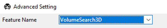
Select the VolumeSearch3D feature from the Features menu in navigate.
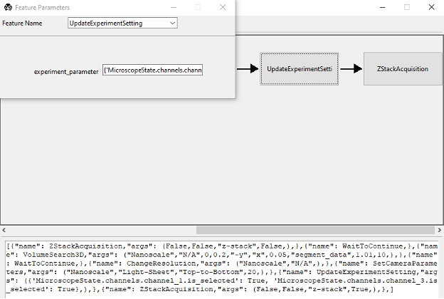
If the feature is not available, you may need create your own version of the feature, which can be done by selecting the Add New Feature menu from the Features menu. This can be done by copying the following code into the Feature Popup Window.
[
    {"name": ZStackAcquisition, "args": (
        False,False,"z-stack",False,),},
    {"name": WaitToContinue, },
    {"name": VolumeSearch3D, "args": (
        "Nanoscale","N/A",0,0.2,"-y","x",0.05,"segment_data",1.01,10,),},
    {"name": WaitToContinue, },
    {"name": ChangeResolution, "args": (
        "Nanoscale","N/A",),},
    {"name": SetCameraParameters, "args": (
        "Nanoscale","Light-Sheet","Top-to-Bottom",20,),},
    {"name": UpdateExperimentSetting, "args": ("({
        'MicroscopeState.channels.channel_1.is_selected': True,
        'MicroscopeState.channels.channel_3.is_selected': True},)",),},
    {"name": ZStackAcquisition, "args": (
        False,False,"z-stack",True,),},]
Confirm that the Feature is Selected:
Ensure that the VolumeSearch3D feature is selected in the features list menu.
Change the acquisition mode to Customized, and select Acquire.
This will open the Feature List Configuration Window.
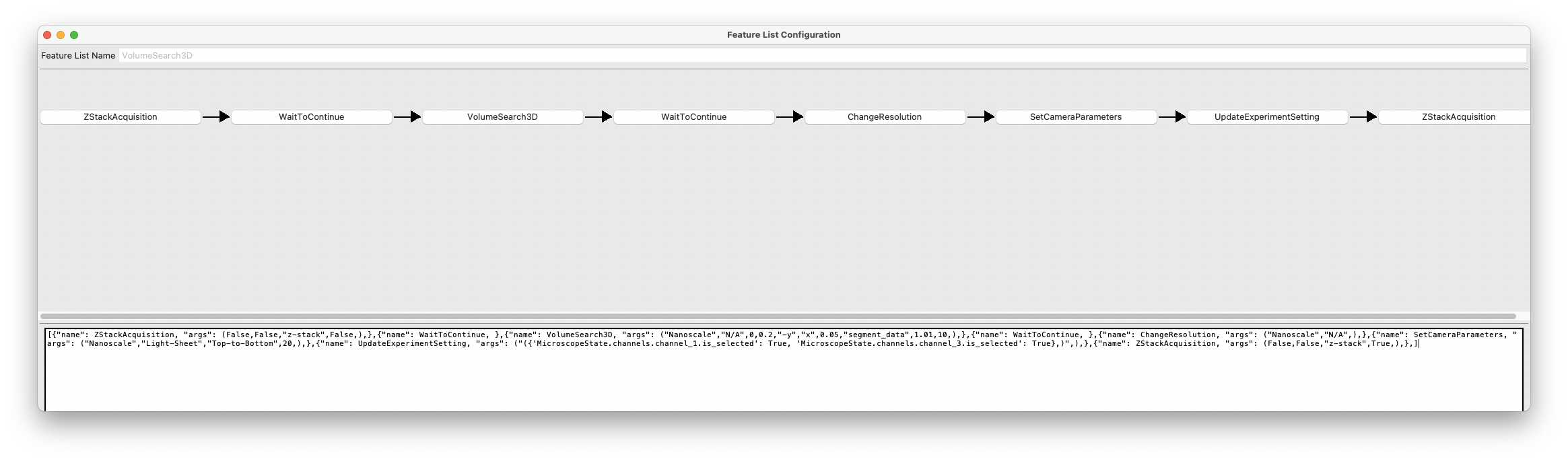
Press the VolumeSearch3D Button in the Feature List Configuration Window:
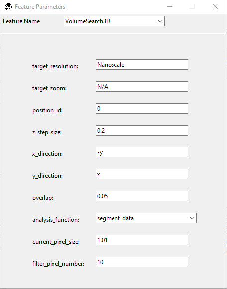
This will open the Feature Parameters window, which is where you configure the VolumeSearch3D feature. It includes the following entries:
target_resolution: Set to Nanoscale. This is the microscope object that we will be switching to upon completion of the low-resolution imaging.
target_zoom: Set to N/A. This is the zoom level of the Nanoscale microscope object, here configured to N/A since it operates at a fixed zoom level.
position_id: Set to 0.
z_step_size: Set to 0.2. This is the step size for the Nanoscale module.
x_direction: Set to -y. This is the direction of the stage movement in the X direction.
y_direction: Set to x. This is the direction of the stage movement in the Y direction.
overlap: Set to 0.05. This is the overlap between adjacent images in the X and Y directions if tiling is necessary.
analysis_function: Input the name of the segmentation function (e.g., segment_data) that will be used to detect objects.
current_pixel_size: Set to 1.01. This is the pixel size of the low-resolution imaging.
filter_pixel_number: Set to 10. This is the minimum number of pixels that must be present in a detected object for it to be considered valid.
Once you have configured the parameters, close the window to save the settings.
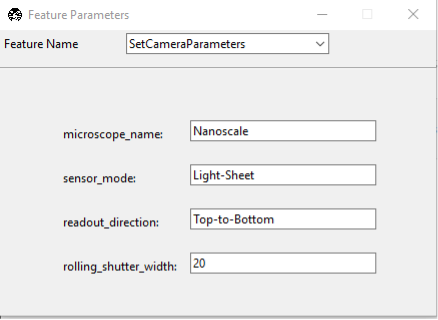
Press the SetCameraParameters button in the Feature List Configuration Window:
If you need to adjust the camera settings between the two imaging modalities, you can do so here. This is typically done to ensure that the camera settings are appropriate for the resolution and magnification of the imaging mode. Here, we specify the target microscope, the sensor_mode (e.g., Light-Sheet or Normal). If imaging in the light-sheet mode, you will also need to specify the readout direction (Top-to-Bottom, or Bottom-to-Top, etc.), and the Rolling Shutter Width.
Once the settings are configured, close the window to save the settings.
Press the UpdateExperimentSetting button in the Feature List Configuration Window:
If you need to change which channels are selected, you can do so here. In this example, the low-resolution imaging was performed for as single channel. Once the microscope switched to the nanoscale microscope object, we select two channels for imaging. This is done by specifying the channel names in the format of a dictionary, where the keys are the channel names and the values are booleans indicating whether the channel is selected (True) or not (False). For example, to select channels 1 and 3, you would use:
{
    'MicroscopeState.channels.channel_1.is_selected': True,
    'MicroscopeState.channels.channel_3.is_selected': True
}
Press Confirm to Begin Imaging:
Once all the parameters are set, press the Confirm button to start the imaging process. The system will first perform low-resolution imaging to identify the objects of interest, apply the segmentation algorithm, and then switch to the high-resolution imaging mode to acquire detailed images of the detected features.